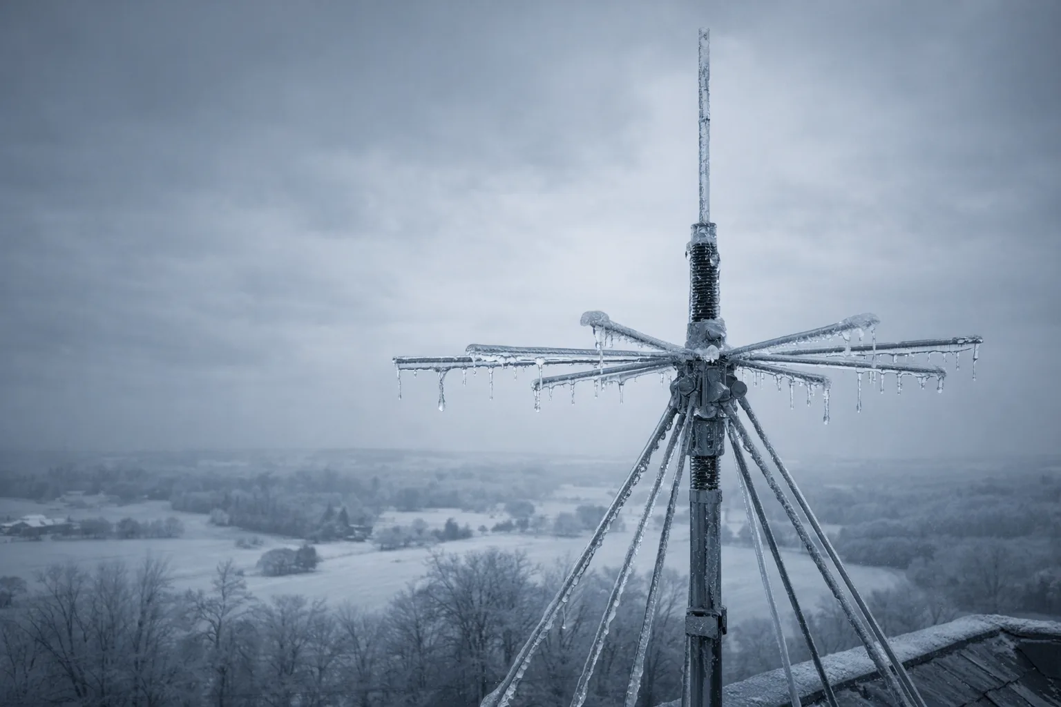
It was a January ice storm in central Tennessee — temperatures dropping fast, freezing rain coating everything in glass — when I realized my scanner setup had a problem. Not the radio inside the house, safely tucked into its Faraday enclosure. The antenna outside. It had been up for about eight months, and the coax fitting had already started to corrode. I lost reception across half my frequency range at exactly the moment I needed to monitor emergency services traffic. That failure taught me more about scanner antenna selection for EMP preparedness than any spec sheet ever could.
I've been running the Diamond D3000N discone as my primary broadband scanner antenna for EMP preparedness for just over five years now. In that time, I've tested it across two locations — a rural property in middle Tennessee and a semi-suburban setup outside Knoxville — through ice storms, summer heat, lightning seasons, and one near-miss grid event from a significant solar storm watch in 2024. This isn't a consumer tech review. It's a system integration assessment built around one core question: does this antenna belong in a hardened post-blackout communication setup?
The answer is nuanced. And the details matter more than the product.
Why Scanner Antennas Are the Overlooked Link in EMP Preparedness
Design brief: Create a vertical frequency spectrum chart (25 MHz to 1300 MHz scale on left axis). Use color-coded bands: NOAA Weather Radio (162.400-162.550 MHz) in blue, HAM 2m/70cm bands in green, VHF/UHF public safety (150-174 MHz, 450-470 MHz) in orange, Aviation band (108-137 MHz) in purple. Include labeled callouts for each band showing what information is available (grid status, emergency nets, fire/EMS/police, situational awareness). Suggest layout: vertical spectrum bar with horizontal information cards extending right. Use professional, technical color palette. Add small icons (weather, radio operators, emergency vehicles, airplane) next to each band.
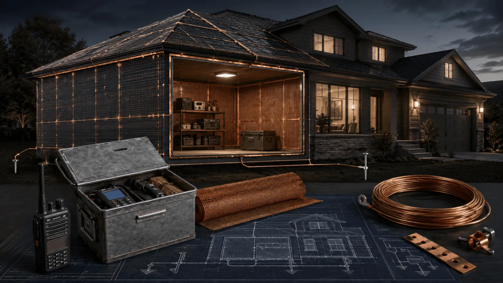
Most preppers spend serious money hardening their radios. Faraday cages, EMP bags, shielded enclosures — the receiver gets protected. The antenna almost always gets ignored. That's a critical planning error because in a post-EMP or post-CME scenario, your antenna is the first point of contact with the outside world, and it determines what your hardened radio can actually hear.
Here's the part that doesn't get discussed enough: antennas themselves are largely immune to EMP damage. A passive antenna — one with no active electronics — has nothing to fry. What EMP events threaten is the conduction path that antenna creates directly into your shielded equipment. An improperly installed antenna and feedline can become an EMP delivery system straight into your Faraday-protected radio. The protection you built means nothing if the antenna cable bypasses it.
For post-event communication, your scanner needs to cover a specific set of frequencies:
- 162.400–162.550 MHz — NOAA Weather Radio, your fastest source of official grid-status and emergency information
- 144–148 MHz and 420–450 MHz — HAM 2-meter and 70-centimeter bands, where amateur radio emergency nets (ARES/RACES) operate
- 150–174 MHz and 450–470 MHz — VHF/UHF public safety, fire, EMS, and local government coordination
- 108–137 MHz — Aviation band, useful for situational awareness near airports and for monitoring federal aircraft activity
A scanner antenna for EMP preparedness isn't a niche accessory. It's the ears of your entire communication strategy. Choose wrong, and your hardened radio is effectively deaf.
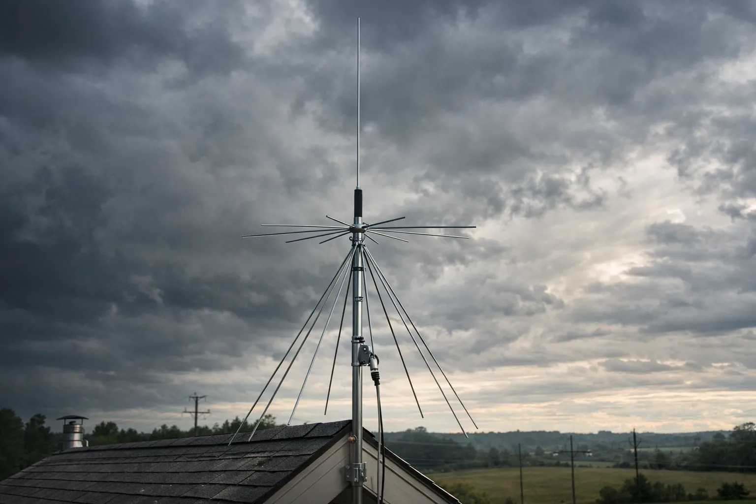
Diamond D3000N Specifications and Why Discone Design Matters
The D3000N covers 25 to 1300 MHz in receive mode, with a transmit capability on select amateur bands. For scanning purposes, that receive range is what matters — and it's genuinely exceptional for a single passive antenna. The discone design (a cone element combined with a disc ground plane) achieves near-omnidirectional, vertically polarized reception across a dramatically wide bandwidth without needing an active amplifier to do it.
Competing antenna types fall short in specific ways for this use case. A standard monopole whip gives you decent performance on a narrow band but degrades badly as you move away from its resonant frequency. A Yagi directional antenna gives you gain in one direction — useful if you know exactly where you're pointing — but terrible for monitoring multiple sources simultaneously. A loop antenna excels at HF and medium wave but drops off at VHF and above. The discone's broadband compromise is exactly what preparedness scanning demands.
Key specifications worth knowing:
- Frequency range: 25–1300 MHz receive, amateur transmit on select bands
- Impedance: 50 ohms, standard for most scanner and amateur radio coax
- Construction: Aluminum elements with stainless steel hardware on the connector assembly
- Connector: PL-259 (SO-239 socket), compatible with most scanner feedlines with the right adapter
- Mounting: Accepts standard 1–1.25 inch mast pipe, compatible with typical rooftop or tower mounting hardware
The aluminum construction is a double-edged consideration for preppers. Aluminum doesn't rust, which matters for longevity. But aluminum oxidizes at connection points, and that oxidation increases resistance and degrades performance over time. I'll come back to how I manage that in the maintenance section.
Five Years of Real-World Testing: What the Data Actually Showed
I'll be direct about methodology here: this isn't laboratory data. It's systematic field observation logged across five years, two locations, and three different scanner receivers. I use a signal strength comparison approach — benchmarking reception quality on known-strength broadcasts at the start of each season and after any significant weather event. It won't give you decibel-precise numbers, but it tells you when performance degrades and why.
Durability held up remarkably well. Across two Tennessee locations, the antenna survived multiple ice loading events, straight-line wind gusts I estimated at 50–60 mph based on local weather station data, and sustained summer heat that regularly pushed surface temperatures above 120°F on the mast. I lost one element junction to vibration fatigue in year three — a hairline crack at the base of one of the upper cone elements. Replacement required only a single element, not the full antenna, and Diamond's parts availability made that a straightforward repair.
Reception quality varied by frequency range. In my testing, performance in the VHF public safety band (150–174 MHz) was consistently strong at both locations. UHF performance (450–800 MHz) was excellent at the rural site with clear horizon lines, and slightly reduced at the suburban site where I had a two-story structure creating partial shadowing at low elevation angles. Low-band VHF (25–50 MHz) and the cellular/digital public safety range above 700 MHz were the weakest performers — adequate but not exceptional. For preparedness use, the frequencies that matter most all fell in the antenna's strongest performance window.
Rural vs. suburban comparison revealed an important lesson: antenna height matters more than location type. At the rural site mounted at 25 feet on a telescoping mast, I consistently received signals I couldn't pull at the suburban site mounted at 15 feet on a chimney bracket. When I raised the suburban installation to a ridge-mounted position at approximately 22 feet, performance equalized. For EMP preparedness planning, budget for height before you budget for the antenna itself.
Weather resilience was the antenna's strongest attribute. Beyond the single element failure in year three — which I attribute to installation tension rather than material failure — the D3000N required no structural maintenance. The PL-259 connection point needed annual attention, but the antenna elements themselves performed without issue through five full weather cycles.
Installation for Hardened Systems: Faraday Considerations and Grounding
This is where most scanner antenna guides stop being useful for preppers. Installation for preparedness isn't the same as installation for hobbyist scanning. Your antenna system needs to be designed so that it doesn't compromise the Faraday protection around your receiver.
The core principle: every conductor that enters your shielded space is a potential EMP ingress path. Your antenna feedline is a long wire that reaches outside your protection and connects directly to your radio. If you run coax from an outdoor antenna straight through your Faraday enclosure wall, you've created a bypass. For a deeper breakdown of enclosure design, see our guide on Faraday Cage Design for Communication Equipment.
Here's the installation approach I use and recommend:
- Install a bulkhead feedthrough connector on the wall of your shielded enclosure. Never pass the coax cable directly through a hole.
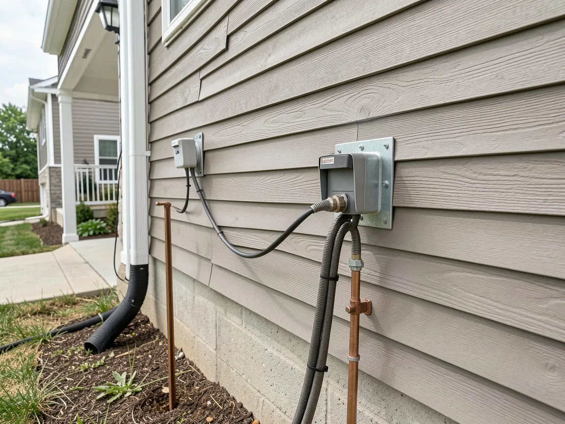
- Use a gas discharge tube (GDT) surge arrestor at the point where the feedline enters your building. This is your first line of defense against conducted transients — both lightning and EMP-induced voltage on the line.
- Ground the arrestor to an earth ground that is physically separated from your building's electrical ground. A dedicated 8-foot copper ground rod driven within 6 feet of the arrestor is the baseline. See our article on Grounding Systems for Preppers: Lightning and EMP Protection for the full protocol.
- Use double-shielded coax (LMR-400 or equivalent) between the antenna and your building entry point. The outer shield provides a second barrier against induced current pickup along the cable run.
- Keep the exterior cable run as short as practical and route it away from other conductors where possible. Parallel runs with power lines increase coupling and increase your exposure.
One operational choice worth considering: some preppers keep their hardened radio disconnected from the antenna entirely when not in use, connecting only when actively monitoring. That approach maximizes protection during storage but creates a gap in passive monitoring capability. Your threat model should drive that decision, not default habit.
Cost vs. Value: Building the Full System on a Preparedness Budget
The D3000N retails in the $80–$110 range depending on where you source it. That's not the system cost — that's the antenna cost. Before you buy, map the full investment:
- Antenna: $85–$110
- Double-shielded coax (LMR-400, 25-foot run): $40–$65 depending on connector termination
- GDT surge arrestor (Polyphaser or equivalent): $35–$60
- Ground rod, clamp, and wire: $20–$35
- Mast, mounting hardware, and weatherproof sealant: $30–$60
You're looking at a total system investment of roughly $210–$330 before the receiver. For comparison, a budget discone alternative in the $25–$35 range built with lighter-gauge aluminum and cheaper connector hardware will save you money upfront and cost you in durability and reception quality within 18–24 months of outdoor exposure. In my experience, budget discones work acceptably for indoor or temporary deployment; they're not a 5-year outdoor solution.
The honest cost-benefit calculation for EMP preparedness: the antenna is the one part of your scanner system that will be permanently exposed to the environment and the one part you cannot protect in a Faraday enclosure. Spending more on the antenna and less on the radio is a defensible preparedness strategy. A $300 radio behind a $25 antenna is a more fragile system than a $150 radio behind a $100 antenna with a properly installed feedline. For context on where your scanner fits in the larger communication picture, read our overview of Post-EMP Communication Plan: HAM Radio vs. Scanner Advantages.
Maintenance Protocol and Long-Term Reliability

Five years of data gave me a clear picture of what actually needs attention and what doesn't. Here's the annual inspection protocol I follow every spring before severe weather season and every fall before ice season:
- Inspect all element junctions for stress cracks or corrosion buildup. Pay particular attention to the base of the cone elements and the disc-to-mast connection point.
- Clean all aluminum-to-aluminum contact points with fine steel wool or electrical contact cleaner, then apply Noalox or equivalent anti-oxidant compound before reassembly. Skipping this step is how you lose 20–30% of your effective performance without any visible damage.
- Inspect the PL-259 connection where the feedline meets the antenna. Reseal with self-amalgamating tape annually. The factory seal degrades faster than the antenna hardware.
- Check mast and mounting hardware for looseness — particularly any U-bolt clamps. Vibration over a season will back off fasteners that were tight at installation.
- Test reception on a known-strength reference signal before and after maintenance. NOAA Weather Radio provides a consistent, always-on reference signal on a fixed frequency. If your signal quality drops significantly from baseline, you have a connection issue, not an antenna issue.
On testing your antenna without a connected receiver: you can perform a basic continuity check on your feedline with a multimeter to confirm the center conductor and shield are intact. For antenna element continuity, a simple resistance check from the SO-239 center pin to the antenna elements confirms the mechanical connections are sound. Neither test replaces an actual signal quality check, but both will catch wiring failures before you invest time troubleshooting the wrong component.
Replacement parts for the D3000N are available through Diamond's US distributor network. Individual elements are stocked as service parts — you don't need to replace the full antenna for a single mechanical failure. That parts availability was a deciding factor in my continued use of this antenna over alternatives that offer no manufacturer support for field repair.
Decision Framework: Is the D3000N Right for Your Setup?
After five years, I don't treat the D3000N as the only answer. I treat it as the right answer for a specific preparedness profile. Use this framework to decide where you fall:
The D3000N makes sense if: You need a single antenna covering HAM, NOAA, public safety, and aviation bands. You're installing for fixed outdoor use with a 3–7 year expected service life. You want manufacturer parts support for field repair. You're building a hardened system and need a reliable starting point for your feedline design.
Consider alternatives if: Your primary interest is a single band (a dedicated 2-meter antenna will outperform the D3000N on VHF HAM). You need a portable, deployable antenna for mobile preparedness scenarios (a roll-up J-pole or collapsible whip is more practical). Your budget is under $150 total including cable and mounting, and you can accept replacement every 2–3 years.
The scanner antenna decision isn't really about the antenna in isolation. It's about what you're monitoring, how permanently you're installed, and how that antenna integrates with the rest of your hardened communication stack. Get those questions answered first. Then select the hardware that fits the answers.
If you're building a serious post-blackout communication capability, start with the grounding and feedline design. Install it correctly once. Then mount whatever antenna fits your frequency needs and budget at that installation point. The antenna is the last decision, not the first. That sequencing is what separates infrastructure hardening from gear collecting — and it's what will determine whether your system actually works when the grid doesn't.